Automatic Self Playing Kalimba V2
May 14, 2020
Intro:
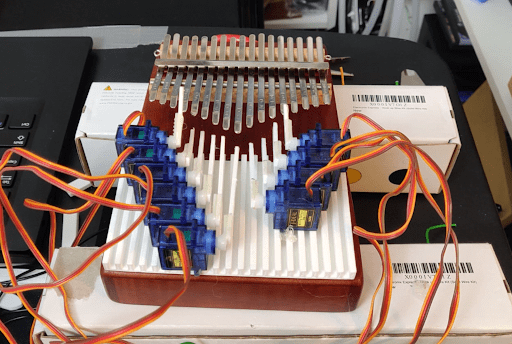
This is the Automatic Self Playing Kalimba V2 (I should shorten this title). Before discussing the AWESOMENESS of this device, I will recap the problems with the previous version. Version 1 was adequate, but there were a lot of issues with its design. The largest one issue was its small range of notes. The Version 1 prototype could only play about one octave worth of notes. This limited the number of playable songs. The second biggest issue was the volume of the servos. I had mounted the servo onto the Kalimba body, so the hissing servo noise echoed inside the hollow body. The recorded audio further emphasized this sound because I placed the microphone inside the sound hole.
Design:
The design process took me the longest to complete. I will explain my thinking in creating this mechanism. Please leave a comment if you have any questions!
I need to design a brand new frame and structure to hold the servo motors off of the Kalimba body, while housing at least two octaves worth of servo motors. I went through many different ideas and designs to solve these issues. Eventually, I decided that the best method to proceed forward was using a linear actuator model to pluck each note. The linear actuator design allows me to stack servo motors on top each other. This design also solved the tertiary issue of insufficient torque. In V1, the long armed servos had much less force behind each of their plucks because the lever arm was too lengthy. This meant that the notes hit by these servos were much lower in volume when compared to the other notes. In the linear actuator design, all racks will be equidistant from their pinions, so the amount of torque will remain constant. This equates to an equal volume across all notes.
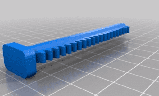
After browsing through Thingiverse, I found a design that turned a servo motor into a linear actuator. It used a basic Rack and Pinion system to achieve the linear actuation. The rack looks like opened up circular gear that is now a straight line. The pinion is the common circular gear that turns to move the rack up and down. I need to figure out how to adapt this virtual rack and pinion design to fit my real life Kalimba.
My first strategy is to do an insane number of measurements to figure out the locations of all servos in 3D space. I realized the better way to approach this design problem was to model the Kalimba in virtual space. If I can create a near perfect virtual version of my Kalimba in CAD, then I can skip all the headache of doing a billion real-world iterations. This will allow me to simulate reality on my computer. Modeling a Kalimba is difficult because there are 17 notes of various lengths. I instead figured out a method to use only one photo and measurement to model the entire Kalimba in CAD. The video below dives into the details of this method.
(Quick video about how to import a real world object into CAD using only one photo and one measurement.)
Once I had created a 3D Kalimba in virtual space, I could begin positioning all my servos relative to each other. I found a 3D model of my servo on Thingiverse. I combined this virtual servo model with the gear model to create one singular part that I can copy and paste. I positioned 14 more copies to not interfere with one another, and to be above their corresponding note. Now that I know where the servos will exist in 3 dimensional space, relative to the Kalimba, I can create a frame that will hold all those servos in place.
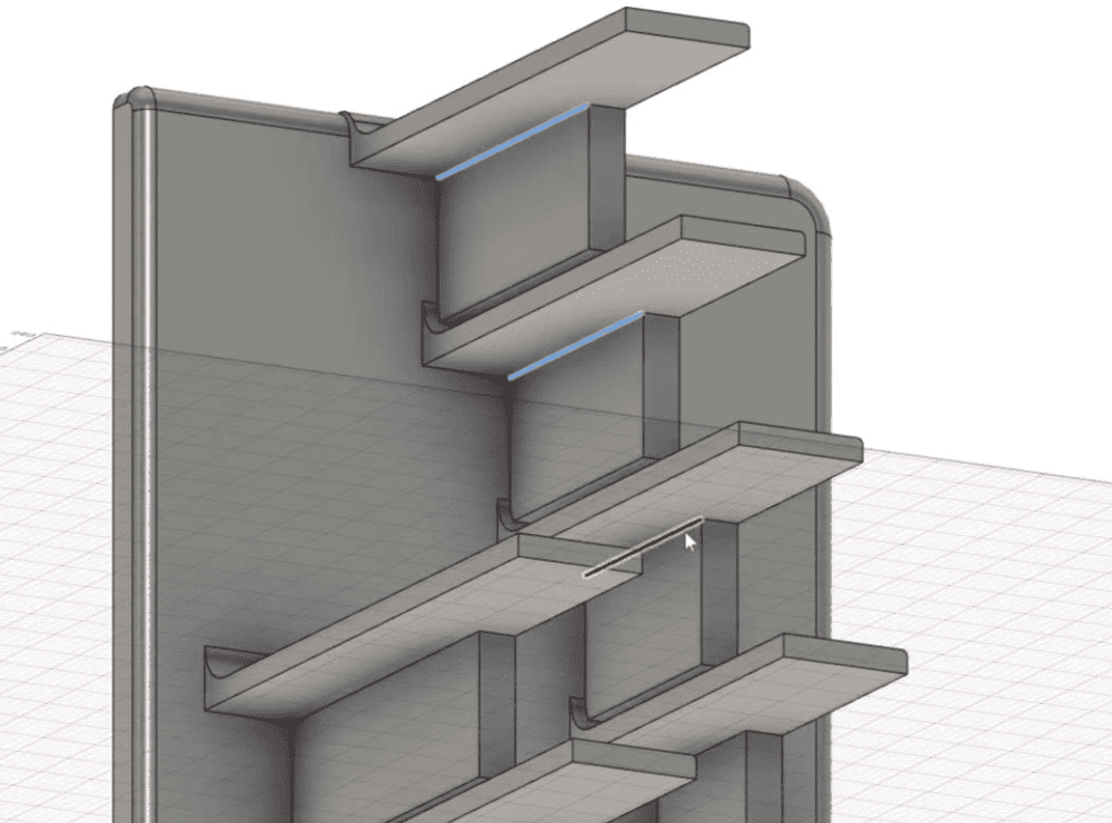
I designed a base plate with a bunch of arms sticking out to meet each servo at their proper position on the left side of the Kalimba. There's a little gap between the frame arm and the servo for the hot glue that will adhere the two. I repeated this same process with designing the right portion of the Kalimba. At the bottom I made sure to add cutouts for registration with the support that will hold these two base plates.
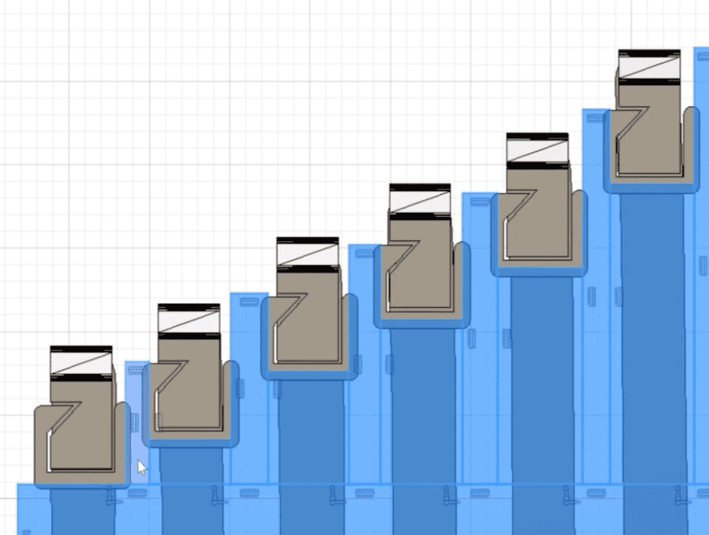
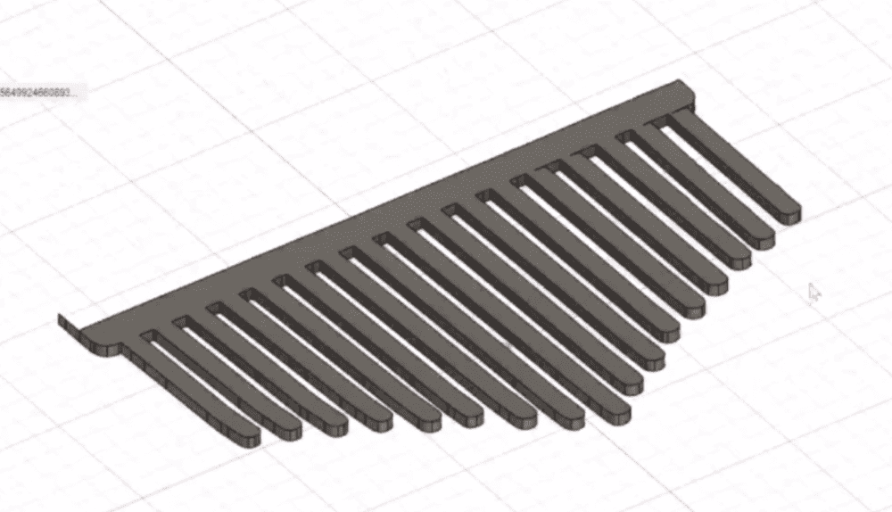
The rack and pinion design was far too large to fit all the linear actuators that needed to cram into the small space. This caused me to redesign the mounting structure that held the rack in place relative to the servo body. I created a small cut into the side of the rack and then had a matching tooth fit into that cut on the frame. Although it was significantly thinner than the original design, it was still plenty sturdy and strong. I used this small tooth design to create a frame that would hold all 15 racks. I separated the rack frame from the pinion frame because I wanted to leave room for adjustment when it was time to assemble everything together.
I printed out a test rack frame to see how well it fit the Kalimba notes….. and man was it off. The frame did not align with the notes of the Kalimba at all. It was far too large, meaning that my calibration for the virtual Kalimba was off. I needed to redesign my Kalimba model to actually fit reality. The mistake seems to stem from using the width of a single metal for calibration, instead of using the entire width of the Kalimba. It is better to use the largest measurement for calibration because any mistake in the smallest measurement will propagate throughout the system. This is how all the pinions became misaligned in the process. The first note is near perfect, the second note is a little off, and by the time we get to the fifth note we are way off. The solution is to first redesign the virtual Kalimba model and print it out to ensure its validity. Then redesign the racks to fit with the new virtual Kalimba.
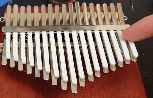
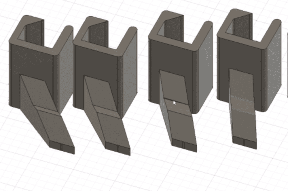
Here comes the next major issue. The racks cannot be closer to one another without redesigning the entire set of frames, racks, and pinions. I had already put in a great deal of work to get this far, so I did not want to start from ground 0 once again. My solution was to create feet at the bottom of each rack that angled inward to play the correct note. This solution involved much less headache, and allowed for a modular solution down the road. If the feet broke upon plucking a metal note, it is easy to interchange new feet without deconstructing the entire mechanism. The feet will be hot glued to the racks, so I can sever the bond to add a new replacement.
Assembly:
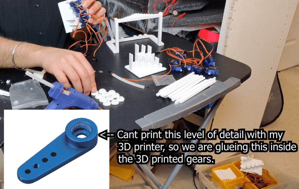
On each servo, is a plastic toothed shaft that the servo horn fits upon. The horn teeth are far too small to print with my 3D printer, so I used the default horn that comes with the servo. The pinion part contains a cylindrical cut out inside its center. I modified the servo horn by cutting off the edge with a soldering iron. The core is hot glued inside the empty cylinder of the pinion. Now the pinion has a method of mounting to the central shaft of the servo. The servo and pinion are now thought of as one part to simplify the process going forward, as it was in CAD.
I hot glued each servo into its proper position on the left and right base plate frame. I then proceeded to mount each section of the frame together to interlock them, as I had described before. Unfortunately, reality is not as kind a virtual space. Parts tend to warp as they print causing things to end up unaligned. In the video, I further explain all the headaches associated in assembly, while showing how the parts interact with one another.
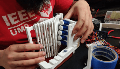
In CAD world, I imagined that the two base plates would stand perpendicular to the support registration holes. However, the holes were not deep enough, so the base plates slipped away when I tried to force the racks to mesh with the pinions. Nothing was holding the pinion base plates at the top, so they would slant. The solution was to design another brace that held the rack frame against the pinion frame. This would provide the pinion frame a support structure to stay in place. This enhanced the strength and rigidity of the frame parts, and allowed me to move onto the wiring.
The wiring was pretty straightforward if you are familiar with using servos. Servos have 3 pins; Power, Data, and Ground. I used a breadboard to wire all the power lines and ground lines in parallel. Then I plugged each data line into its own unique pin on the Arduino. Servos require the Arduino PWM port to send commands. Luckily, the Arduino Mega has exactly 15 PWM ports, so I had the perfect amount to control every servo. Servos can only move between 0 degrees and 180 degrees. I tested each servo to make sure that all can turn up and down between 0 - 180.
Testing and Calibration:
I assembled the core structure, and it (fingers crossed) appeared to be functioning. Now I could begin the testing and calibration phase. When I mesh the racks with the pinions, I first make sure to turn all servo pinions to their max height. Since half of the servos are facing the opposite direction, one side has 0 as the max height and the other has 180. This meant that for downward movement, I would have to add to half the servos and subtract this from the other half. This is a bit confusing at first, but it is easily ignored by coding this into the movement functions. This avoids future headaches and troubleshooting.
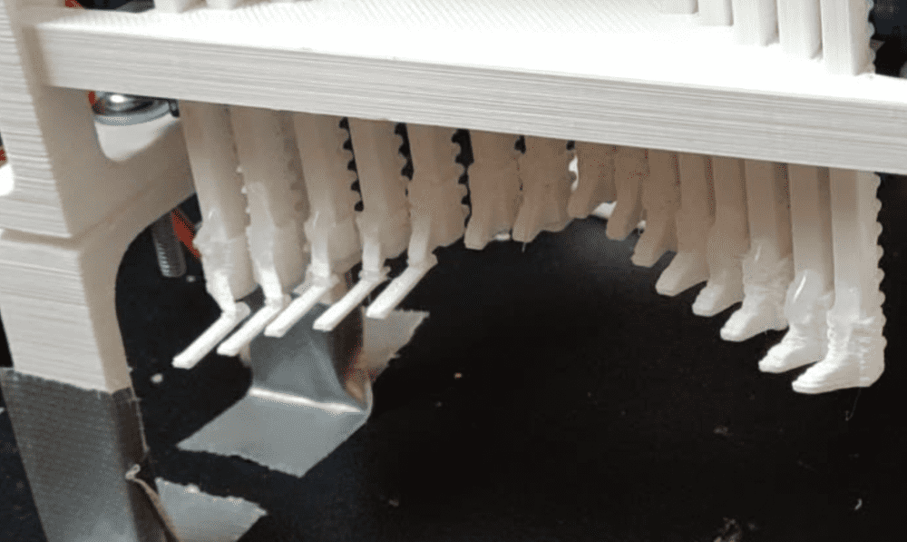
When the racks and pinions are meshing, I could begin measuring the distance each servo has to travel to pluck its corresponding note. I hard-coded these servo distance values into the movement functions. Another major issue arose when I tried to pluck a note with the feet. The feet are too rigid, so the whole apparatus moves up when a foot presses on a note. The 3D printed part for the foot was too stiff, so it could not deform to pluck the metal note. My solution was to create a thin 3D printed rectangle as the plucker for the note. I adhered this part to the bottom of the foot. It stuck out a few centimetres, allowing it to bend up or down to pluck the note. I referred to these rectangles as toes, since they are sticking out of the feet.
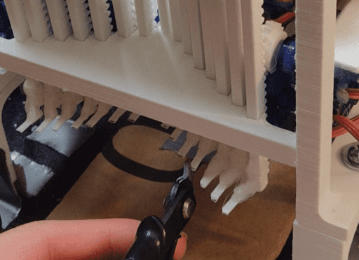
At times, the toes appear to also bite into the metal note too much and cause the whole apparatus to push upwards. There's too much surface area of the toe going into the note, so I had to trim all the toes down to an angled tip rather than a flat tip. This would lessen the surface area, so that the toes could not bite into the note as much. As I refined the edges of these toes down, I arrived closer to near perfection in plucking each metal note. However, every once in a while a toe would bite into the note so hard that it would again push the whole structure up, popping everything out. This was an incredibly frustrating process to overcome. With practice though, I became extremely robust at re-calibrating the racks and pinions. I show and explain this process in great detail towards the end of the video.
End Product:
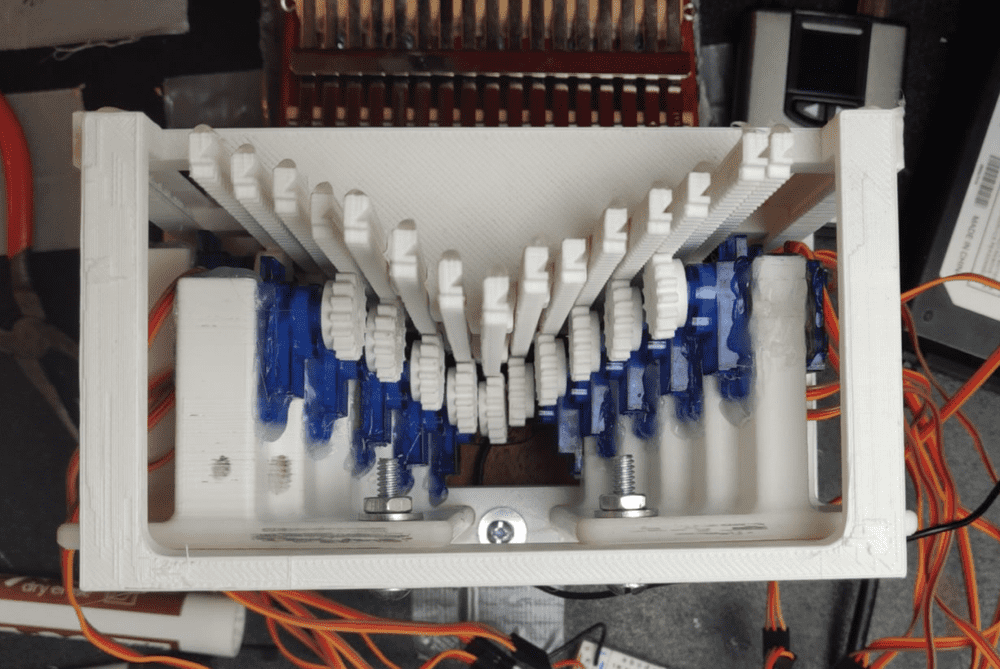
After a many hours of testing, I confirmed the apparatus could pluck each note with similar torque. I then glued all the frame pieces together to create a near permanent bond. At this point in the project timeline, I had been working on this for over a month and wanted closure on the project. This meant skipping the step of designing a bottom that aligns the Kalimba, and using tape as a temporary method to hold everything down on my table.
I wrote functions, to move each servo up and down, in the calibration phase, so programming a song was a matter of calling each function at the correct time. I already knew how to read treble clef because I played violin as a kid. Bass clef was easy to learn since it is two notes down from treble. This made it easy to decipher piano sheet music into function calls and delays. The main limiting factor was that I could only play music in C major because those are the only notes on my Kalimba. Luckily, many songs are already in C major, so I was able to showcase a good couple songs in the finale of this video. I also made a Minecraft Medley video, since half of its songs are in C major.
In the future, I plan on improving this project. I aim to reduce the hissing originating from each servo. I also plan on implementing MIDI functionality, so programming future music will be far more streamlined.