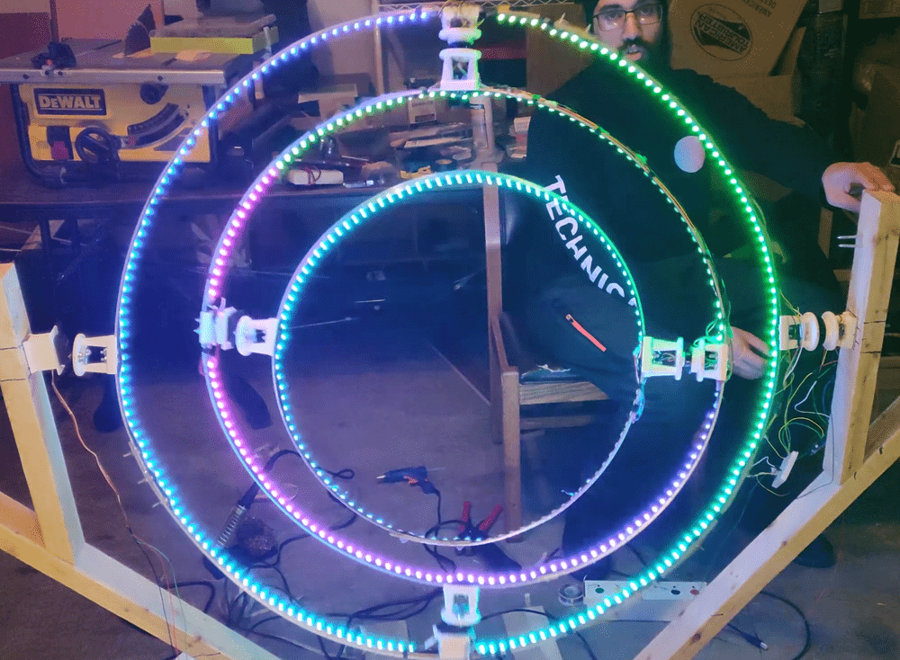
This is a Spinning Armillary. It is often incorrectly referred to as a gyroscope and represents planetary orbits. This particular Spinning Armillary consisted of three concentric metal rings. Each one mounted at a 90 degree offset from one another. The rings contained LEDs, servo motors, and slip rings to light up and autonomously rotate.
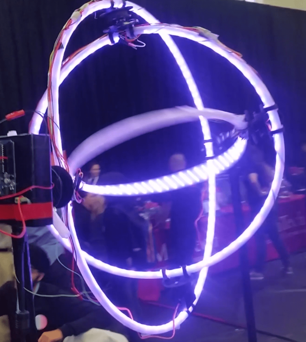
I tried to create this same Spinning Armillary last year, but the first iteration was a fiasco. It failed because I used the incorrect parts and had rushed the entire process. Rather than using metal bars as the skeleton for the rings, I used plastic tubing. My hope was to have the plastic act as a diffuser for the lights, so the whole ring would glow. This somewhat worked, but the main drawback was its structural integrity. It was flailing around because plastic tubing is flimsy. I wasn’t able to make it as large-scale as I wanted in the end due to its lack of strength. I was also forced to fix and repair parts because it was breaking itself apart the longer it ran. I was able to get this first prototype working in the end, however I wasn't able to make it as spectacular as I had hoped.
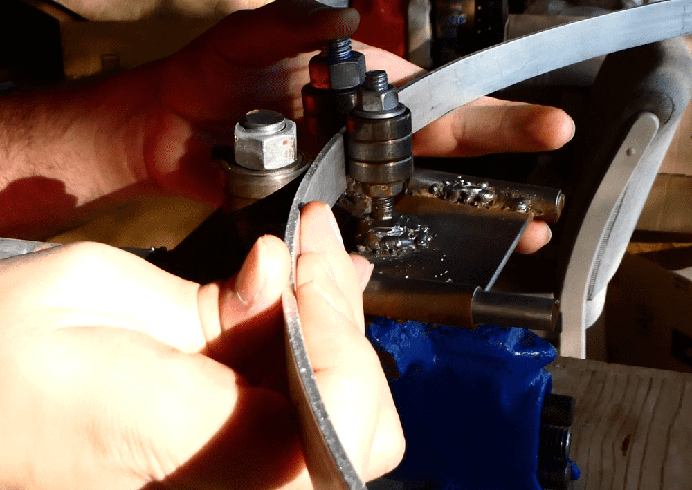
If I wanted to create everything out of metal, then I needed to figure out how to create perfect metal rings. I threw around many ideas to figure out how to obtain metal rings. One idea was to scavenge around junk yards and find old bike wheels, since they are literal metal rings. In the end, I decided to try and fabricate them myself. My plan was to use a roller bender to bend metal bars into a constant radius circle. I was going to buy a roller bender that already worked, but after understanding how simple the machine was I figured that I could make my own version. A secondary reason for wanting to construct my own roller bender was to learn how to weld. I wanted to learn metal work for the longest time and this was the perfect excuse to learn how to weld. I bought a Flux Core welder, since I didn’t have a 220V outlet to use for this and I was still learning. I would rather mess up with a cheaper Flux Core welder than a more expensive TIG welder. I was able to make a crude roller bender out of nuts, bolts, and bearings. I then used that to bend the aluminum bars into a constant radius circle to make the aluminum rings. I used some JB Weld to epoxy the metal bars at the ends to force the ends into holding a proper metal ring shape.
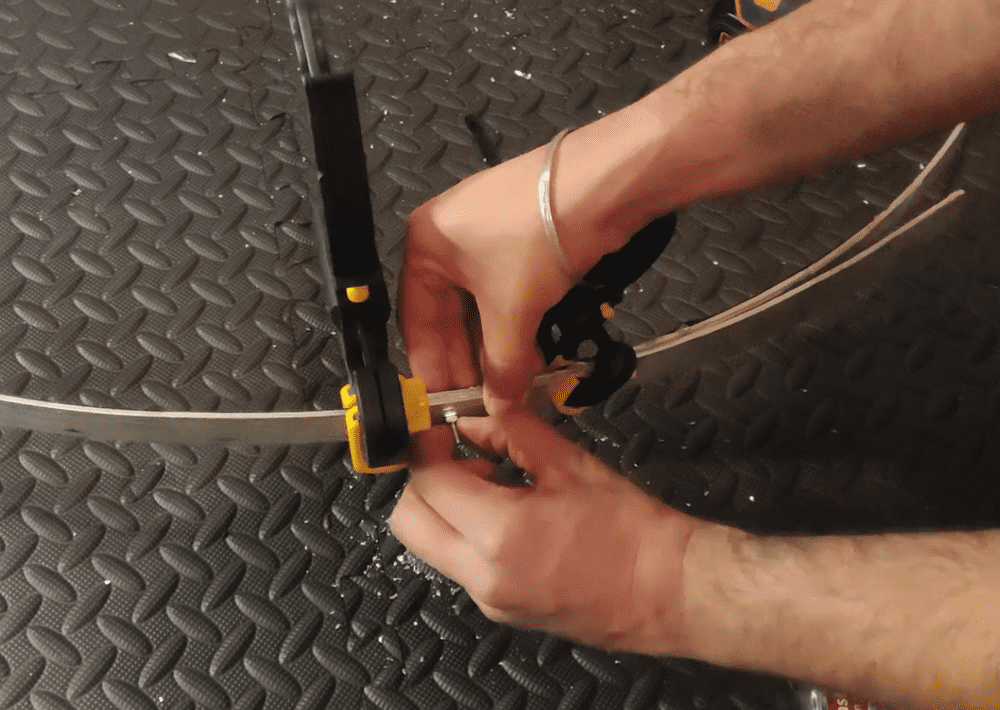
The inner part of the rings will have LEDs. To ensure no shorting across the bare metal, I applied some electrical tape to the inner part of the rings. The tape was wider than the ring, so I cut the tape flush with the outer edge of each metal ring. Unfortunately, the JB Weld did not stand up to the force of the metal trying to unbend itself. I suppose my makeshift roller bender wasn’t the best at creating a full circular shape. It was unable to tack the ends of the metal bars into maintaining the ring shape. My solution was to drill holes in the aluminum and apply nuts and bolts to force the ends together. This made sure that the rings maintained the complete circular shape.
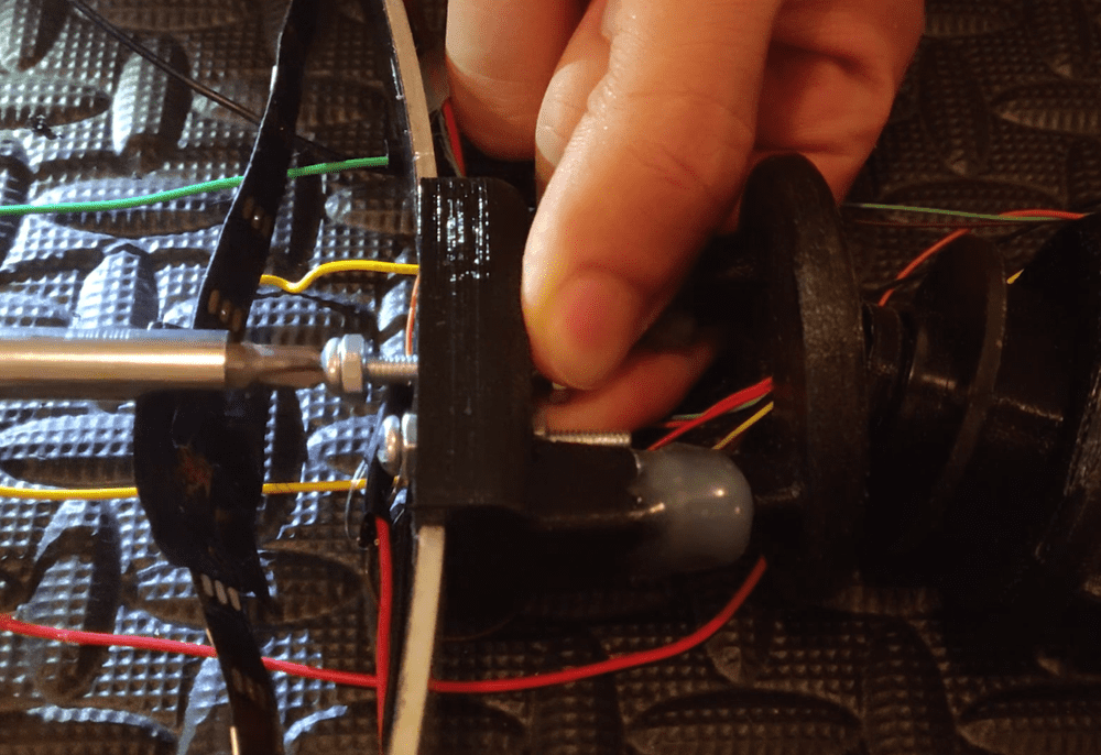
The next step is to design and build a set of brackets to hold the rings together in relation to one another. The picture above shows the old brackets. They appeared to be promising, yet they snapped because they were too fragile. The remedy was to increase the infill of the 3D printed part. The original brackets had an infill of 10%. I bumped this up to 100% because I was running out of time and was paranoid about the constant breaking. In hindsight, the graph of strength to infill is sigmoidal, meaning that there are diminishing returns the higher you go. If I redid this, I would choose something around 70% to 80% because it would have been a much faster print with the same level of strength.
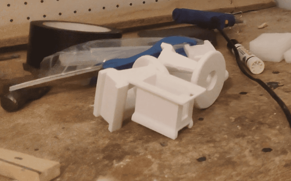
In my paranoia of strength deficiency, I also purchased thicker nuts and bolts. This meant that I had to re-drill all the holes to be wider to reuse the old mounting points. The first step was drilling the holes and then putting in the nuts and bolts to mount the brackets of the slip ring. Once I attached the brackets to the rings, I could secure the outer housing of the slip ring inside the bracket. I then did the same for the back bracket, and screwed the brackets onto the metal ring.
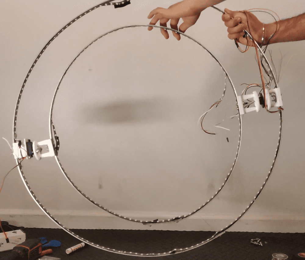
The next part was mounting the brackets of the servos onto the rings. Every servo comes with a mounting brace, often called the Servo Horn. This horn allows you to mount anything on the shaft of the servo. The servo horn has holes already set in place for you to screw into. I used these mounting holes to mark where I should drill holes on the 3D printed front servo bracket. After I drilled matching holes into the front bracket and horn, I secured the horn to the servo. I then mounted the bracket onto the horn. The order of operations is crucial here. Mounting the 3D bracket onto the horn first would prevent me from mounting the horn onto the servo. This process is the same over and over again for the other two sets of brackets, so rinse and repeat.
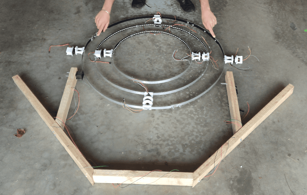
The outer ring will also spin, so it needs to have a frame surrounding it to hold it up right. I made a quick frame out of some 2x3s cut into a U shape. This was a temporary frame, but I actually liked the way it looked, so I left it in that shape. It looks good sitting on the floor, but it would look gorgeous standing up proud among a crowd of people. Thus, I decided to make a pillar stand as a base for this to sit on. I mounted some legs to this pillar for it to stand upright. This pillar was massive; it stood tall and proud above me. This looked awesome, but I could not work on it when it's this high up in the air. I made some temporary legs for it to stand, so I can test it and get all the wiring done. This allowed me to troubleshoot the Spinning Armillary before final deployment.
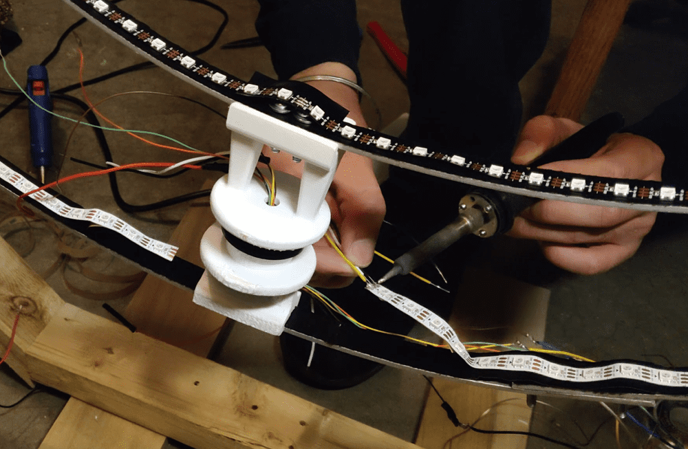
Now that I have secured the brackets, motors, and slip rings in place, I can get to the MOST LIT part of the project; the LEDs. I am using the WS2812B standard of LEDs because each individual light is indexable. I have already completed the first two inner rings, so I will show and explain the large outer ring. I soldered wires to the Power, Ground, and Data line of the LED strip and tested it with an Arduino. Soldering in the air is one of the most difficult methods of soldering that I have done. My solution to this was to put a dollop of solder on each pad of the LED strip. Then I put the wire against the pad and re-melted the solder, so the wire sticks to the pad itself. To avoid mechanical stress to the solder joint, I covered the area in hot glue. This ensured that wire will not pull off the solder pad if it gets tugged or tangled. Additionally, I made sure that no wires would short by applying electrical tape to all solder connections. I then glued all the wires down to the frame to make it look nice and clean. This also ensures that nothing gets tangled up in the future. I then peeled off the layer covering the adhesive back on the LEDs to attach them inside the metal ring.
I didn't care for the light wood color, so I applied some varnish to the wood to give it a better look. The last step is to set it up and see how well it runs!