Prologue
Like many other kids, I grew up on the INSANE AWESOMENESS of DBZ and Naruto. The amazing fight scenes, ridiculously overpowered characters, and ludicrous plot lines had me hooked harder than any candy or soda ever could imagine. I used to watch an unhealthy amount of Toonami, back when it was still a staple on Cartoon Network. This fascination with anime grew into a lifelong interest as I grew older. I watched all of Naruto and Naruto Shippuden, fillers, movies, and all. Shows like Naruto will always have a special place in my heart.
WARNING - The rest of the article will contain some spoilers for Naruto. The show finished several years ago, however if you still have not seen it, and wish to in the future, tread forward with caution.
Idea
Naruto has two defining techniques that he literally spams anytime he gets in a fight. Watch any of his fight scenes and you’ll see him use Shadow Clones, Rasengan, or both. Actually, he can’t even perform the Rasengan without a Shadow Clone for most of the show. I really wanted to make one of these techniques come true in real life. Since I am not yet skilled enough at cloning, I decided to go with the Rasengan.
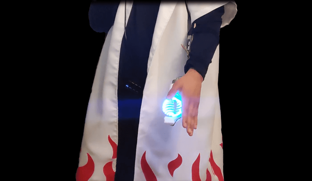
First off, since I cannot use a clone, in order to stay true to the anime I will be cosplaying as a character that can use the Rasengan without requiring a shadow clone. Therefore, it would only be fitting to dress as Minato Namikaze; the 4th Hokage and inventor of the Rasengan. Secondly, I have not mastered control of my chakra yet, so I will be creating a glowing ball of swirling energy using LEDs and a motor. With all that in mind, let’s get into prototyping.
Design
I need to figure out how to have a spinning ball of LEDs safely fit in my hand. Like with many projects the best first step is to mock something up in CAD, in order to flesh out the problems and solutions. I use Fusion 360, since it is free to use, and easy to learn on your own (Leave a comment below if you have any questions about using Fusion 360).
I have this WS2812B LED ring. WS2812B LEDs are smart RGB LEDs. Each one has a chip inside that allows them to be individually indexable. This pretty much means that I can individually program each one to be a certain color, separate from the other LEDs, using an Arduino or any other microcontroller.
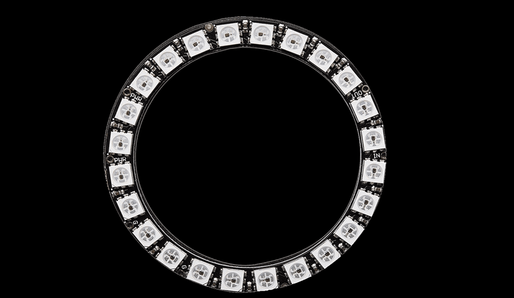
My plan is to spin this LED ring to create an LED orb, thus making something that looks like a glowing ball of swirling energy. In order to spin the LED ring, I will attach it to a motor. Now here comes the trouble. I need to be able to write data and send power to the LED ring but it will be spinning, so the wires would get tangled up.
One solution is to have a separate power source and microcontroller all mounted on the LED ring, so they all spin together and no wires get tangled. The normal Arduino Uno is too large, so I would need a smaller Arduino Mini to get this to work. The LEDs draw a decent amount of power, therefore I would have to go with some sort of LiPo battery system to meet the required demands. This is all definitely possible to create, however there is a much simpler solution to implement.
There is this amazing electronics component called a Slip Ring. A slip ring allows you to transmit power from a stationary structure to a rotating structure. In this case, we have the frame and motor as the stationary structure, and the LED ring as the rotating structure. We can now send power and data to the LED ring through the slip ring, while avoiding a tangled mess of wires and without needing a separate power source and microcontroller.
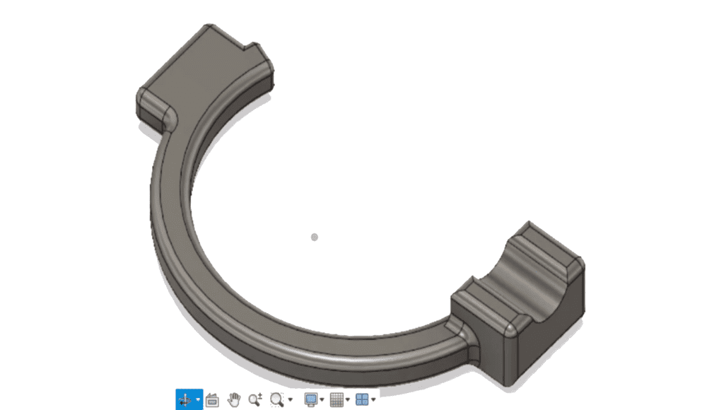
I will attach the slip ring to one side of the LED ring and the motor to the opposite side. This will give stability to the LED ring, since it has two connection points, and will simplify the assembly process. The frame is designed to fit all of these requirements. It has a mounting point on one end for the slip ring, a curved spine to account for the rotating orb, and another mounting point on the opposite end for the motor.
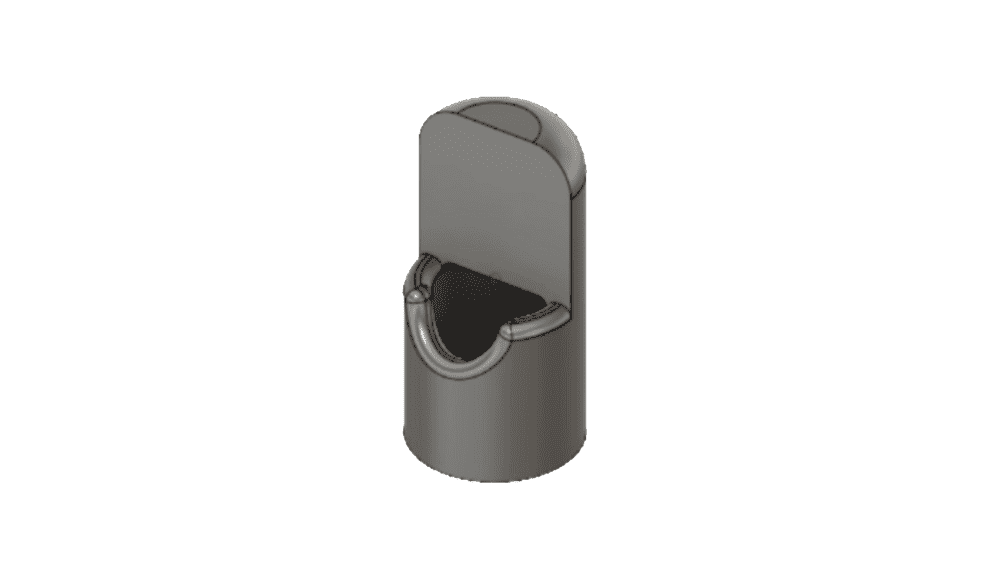
Since the slip ring has no mounting point on its rotational side, we will need to create our own. I designed this small sleeve that slides onto the front and leaves a little gap for the wires to come out. The LED ring will mount onto the flat square section just above the wire gap. This creates a large surface for the LED ring to bond to the slip ring.
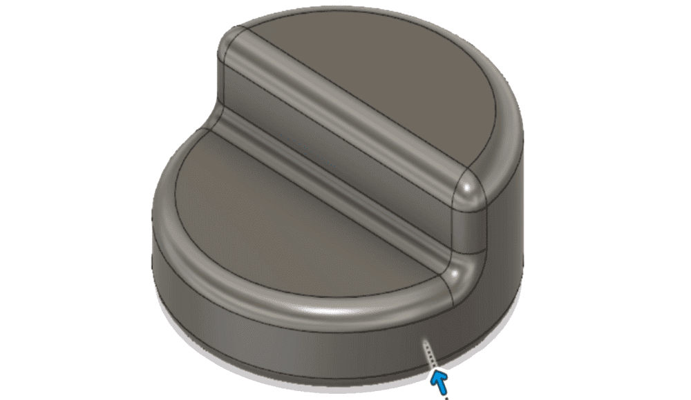
The servo motor will be perpendicular to the LED ring, so it also does not have a mounting location. I designed this quick bracket that acts as a middle man, so both the motor and LED ring have a large surface area to bond together.
Prototype
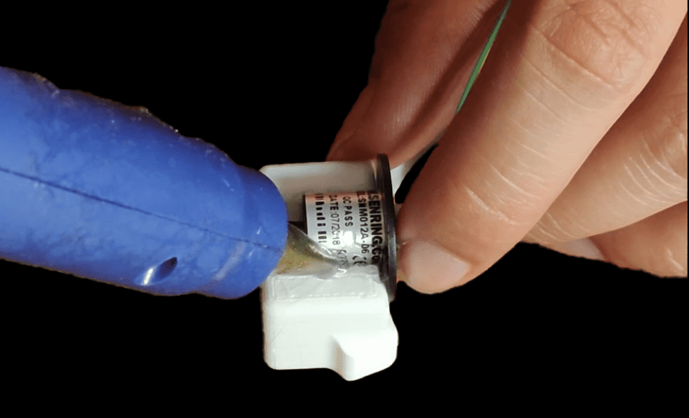
The first step in assembly is laying out all the parts and making sure they fit together. Once I confirmed the fit was proper, I proceeded to hot glue everything together. Hot glue creates a relatively strong bond that can still be broken if you apply enough force. I glued the slip ring onto the frame and ensured that it was leveled properly. Then I glued the 3D printed sleeve onto the front and tacked the wire down, so they didn’t interfere with the flat square area intended for mounting the LED ring. I copied these steps in order to mount the servo motor and bracket on the opposite end.
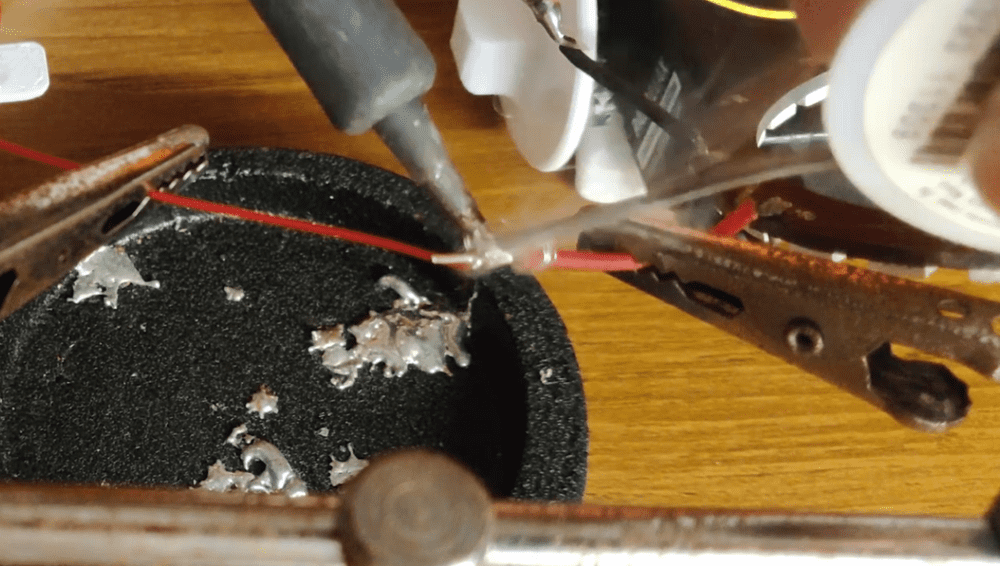
The next stage is soldering the wires. Before we glue the LED ring down we need to test everything that works electrically. Soldering can sometimes result in fault connections and troubleshooting headaches down the line when things do not work. To avoid these problems I made sure to test each component individually throughout assembly. Here is the order of events I followed to ensure proper functionality:
- Plug the Power, Data, and Ground lines of the LED ring into an Arduino to make sure that all LEDs worked. I talk more about using WS2812B LEDs here.
- Do a continuity test on the wire of the slip ring to ensure that there wasn’t a break internally in the wire. If you aren’t familiar with Continuity tests, click here.
- Solder the slip ring wires to the LED ring.
- Do a second Continuity test, this time from the back of the slip ring all to the solder joint. This ensures that the solder joint created a proper electrical connection.
- Plug in the slip ring wires into the Arduino. If the LED ring lights up properly then there are no issues with the electrical connections. If some strange behaviour arises in the future, the electrical connections can be mostly ignored, as a potential problem, since we went through this process.
- The last step is to make sure that your electrical connections are contained. If you have heat shrink tubing, then use that to cover your solder joint. I only had electrical tape on hand, so I used that to cover my solder joints.
Now that we’ve assured everything works electrically, we can mount the LED ring onto the two mounting brackets. It is important to make sure that the ring is perfectly centered. I applied the hot glue to both brackets, positioned the ring in dead center as best as I could, and then held it there as it dried to ensure that it did not move off center. I glued all the extra wires down to the back of the LED ring, so they did not get tangled while spinning.
Time to test out the Servo Motor….. Apparently I am an idiot because I forgot that Servos do not spin fast. They compromise higher speed for higher torque, which means that I cannot use this servo motor unless I hack it open and change the gear ratios inside.
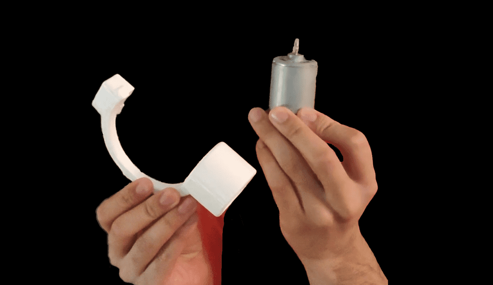
Luckily, I have this spare DC motor. It is around the same size, it just has a different form factor. All I need to do is redesign the Servo motor end of the frame to fit this DC motor. Another stroke of luck was that I used hot glue, so it was pretty easy to break the slip ring off the first frame and mount it to the new one.
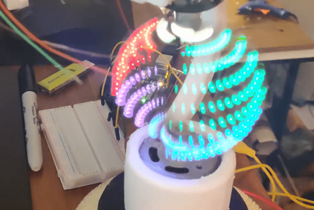
After assembling the new design, I wired up all the components to run off of the Arduino. Moment of truth, I plugged in power and presto… IT ACTUALLY WORKED!!!
Final Product
We’ve confirmed the core functionality of the device; now it is time to clean it up and figure out a way to mount it to my hand.
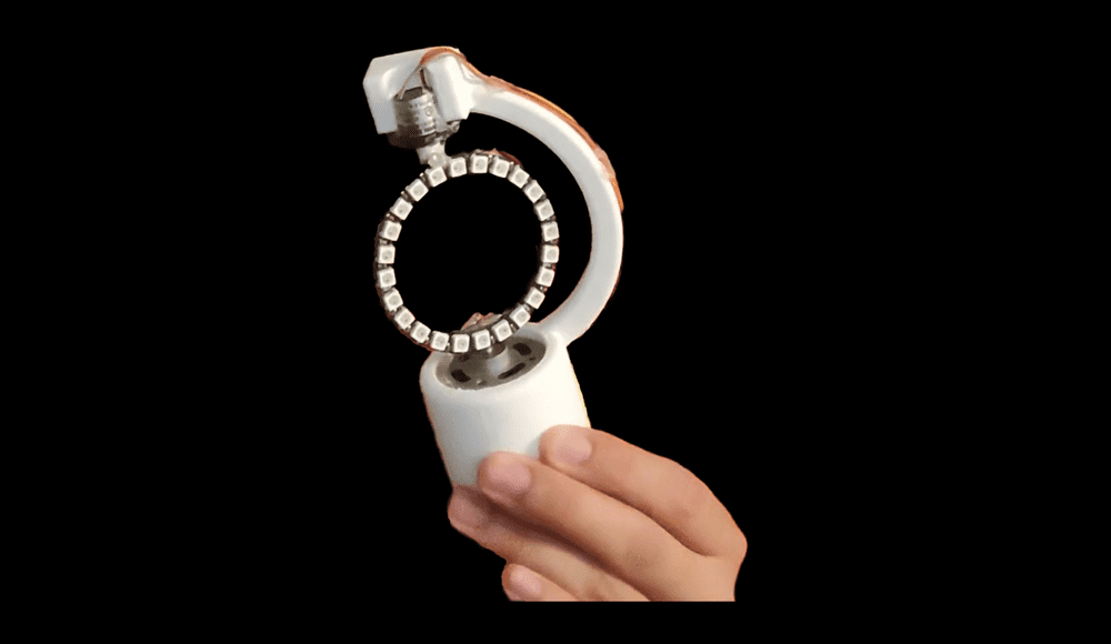
I cleaned up all the remaining wiring by gluing the wires on the other end of the slip ring along the curved frame spine. I had the idea to use a ruler as a mounting surface. My forearm is a bit longer than a ruler, so it won’t interfere with my elbow. It also has a large amount of surface area, so I will be able to mount all the components on one side while having it strapped tight against my arm on the other side.
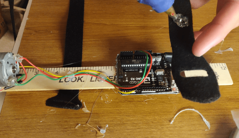
I positioned the ruler along my arm to figure out where it felt best to mount it on my arm. I then hot glued the 3D printed frame, Arduino, and wiring to the ruler. To attach the ruler to my arm I also glued two velcro straps to the back of the ruler. AND VOILA, we have completed the LED Rasengan. The power source is a USB phone charger battery pack that I hold in my pocket.

Last step is to dress up like Minato by wearing his cloak, strap on the LED Rasengan, and run around like a GIANT WEEB!!!!